Circuit Diagram Buck Boost Converter
Wednesday, August 26, 2020
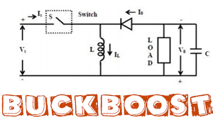
Following circuits may be also useful to you. Connect capacitor in parallel to load.
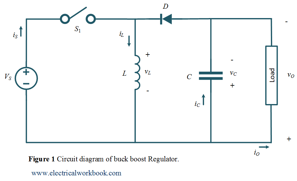
 Circuit Diagram Of Buck Boost Converter Download Scientific Diagram

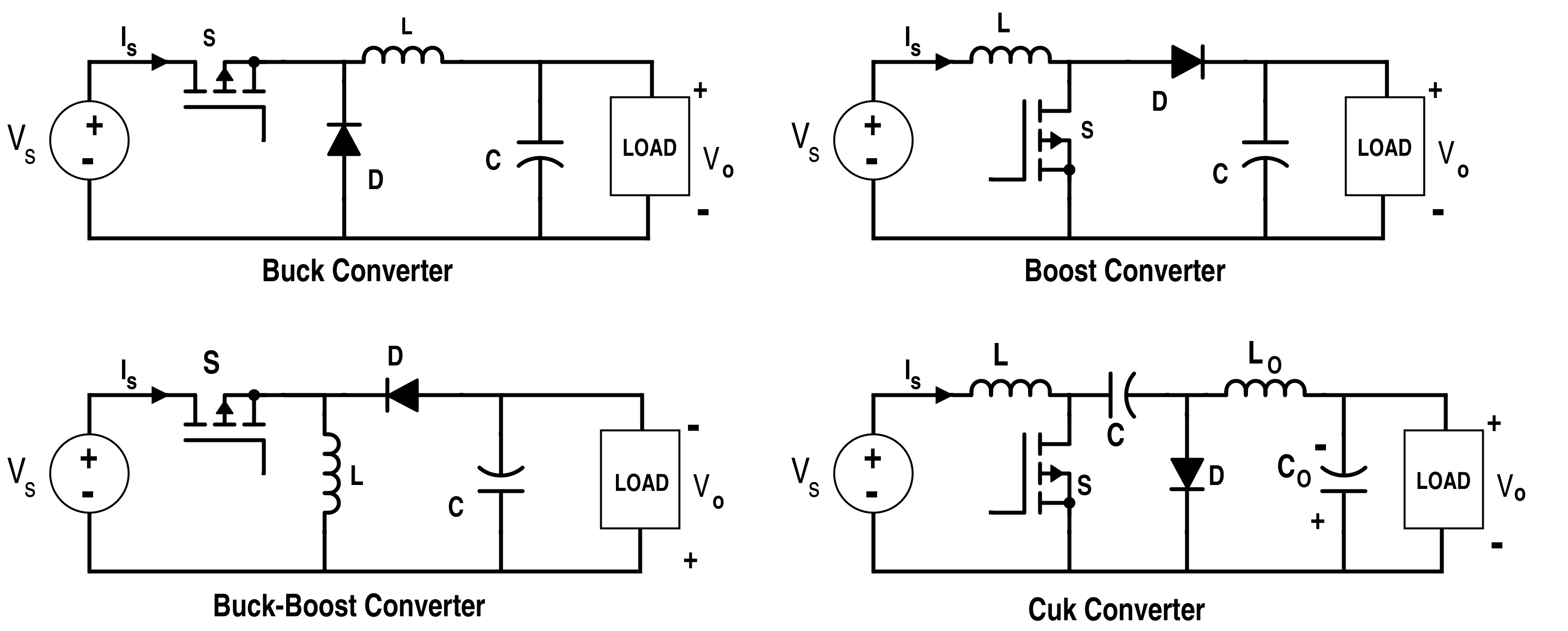
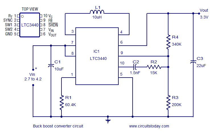
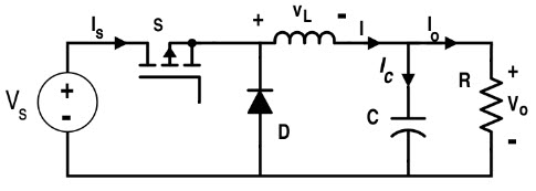
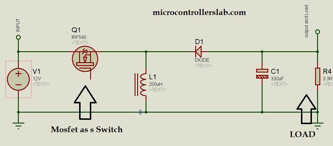
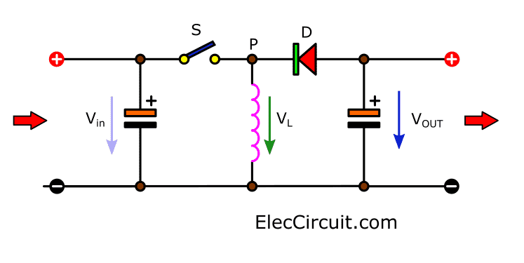
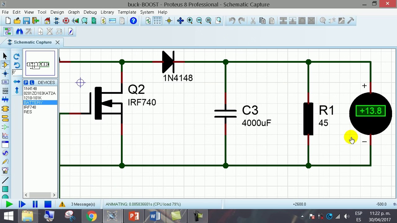
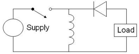
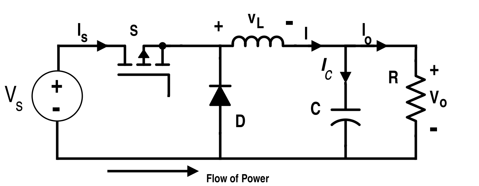
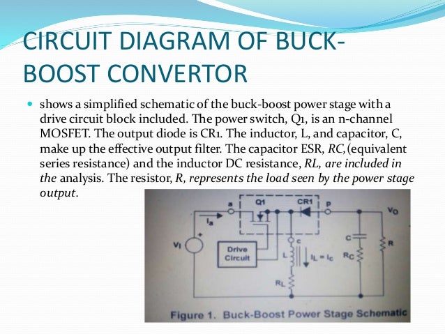
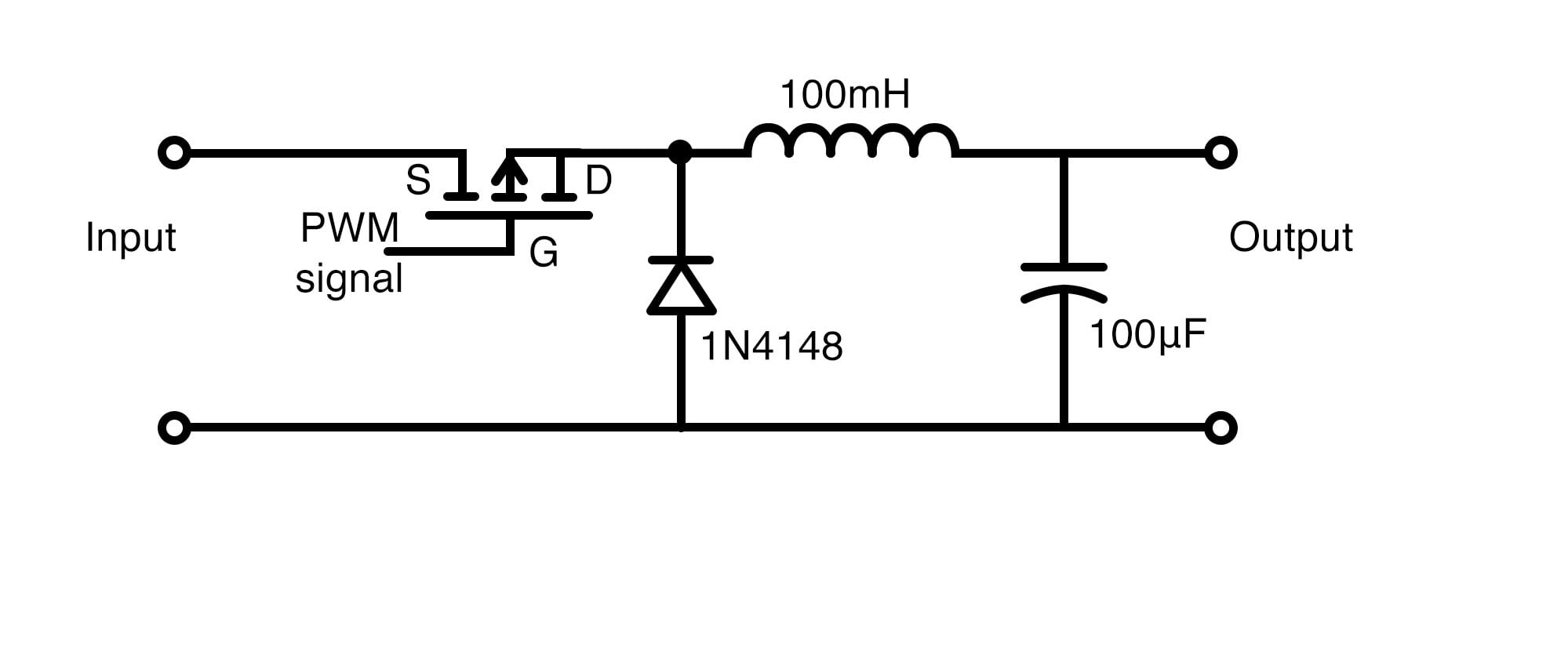
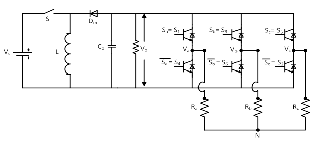
Circuit diagram buck boost converter. A circuit of a buck boost converter and its waveforms is shown below. Input voltage can be between 27 to 42v. Buck boost converter circuit diagram.
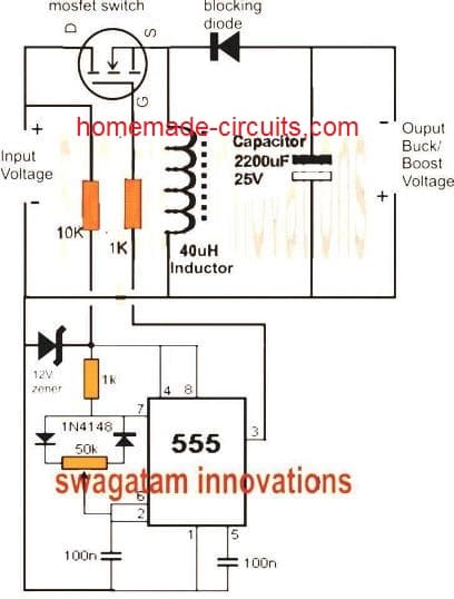
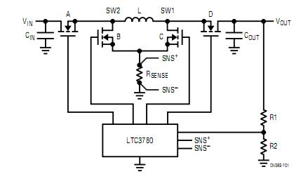
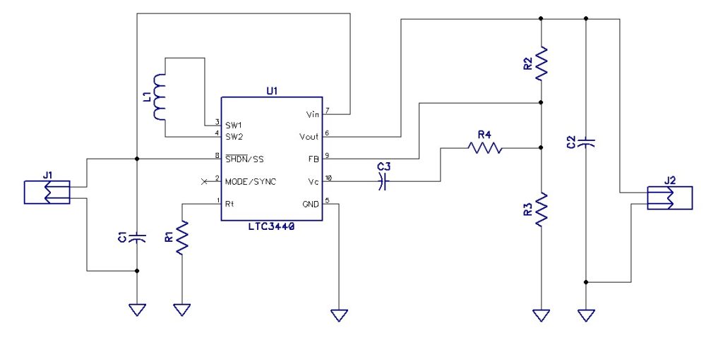
Buckboost converter using ltc3440. C1 to c3 are ceramic capacitors. With an increase in the mosfets on time the circuit starts getting transformed into a boost converter while with the mosfets off time exceeding its on time results in the circuit behaving like a buck converter.
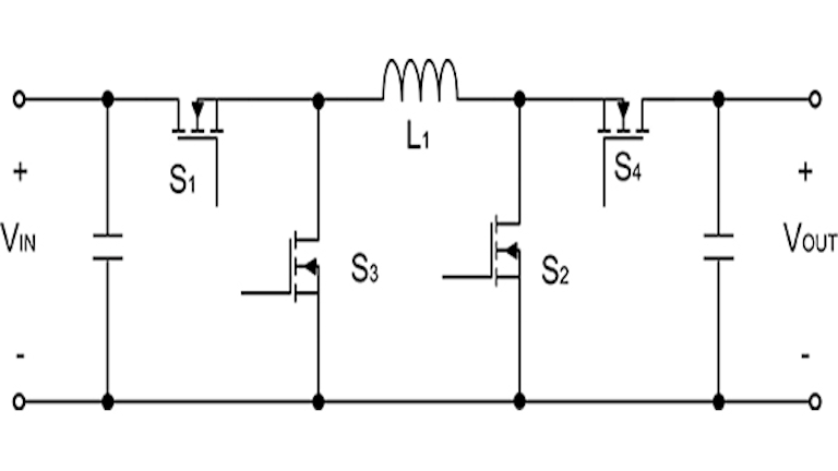
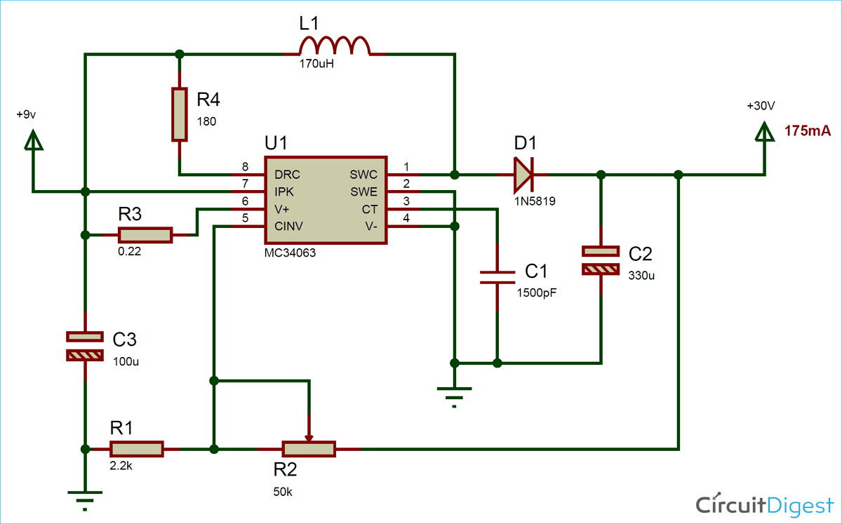
It is a class of switched mode power supply smps typically containing at least two semiconductors a diode and a transistor although modern buck converters frequently replace the diode with a second transistor used for. And if d 05 the output is smaller than the inputbut if d 05 the output voltage is equal to the input voltage. L1 can be a toroid potcore or shielded bobbin inductor.
What is a buck boost converter. A buck converter step down converter is a dc to dc power converter which steps down voltage while stepping up current from its input supply to its output load. 5v buck regulator using lm2678.
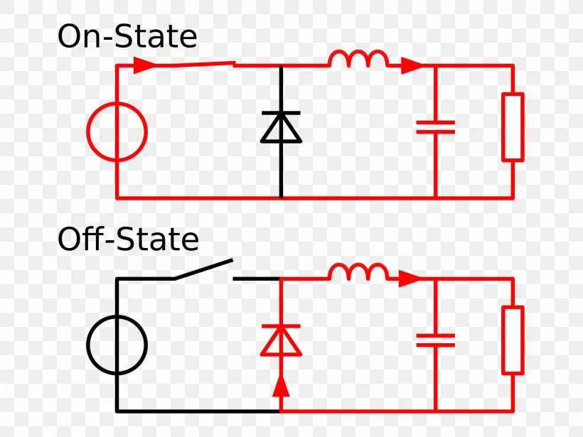
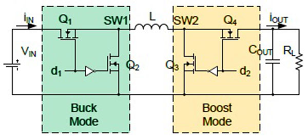
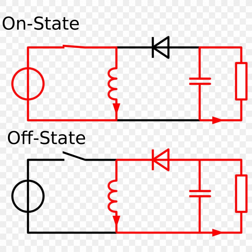
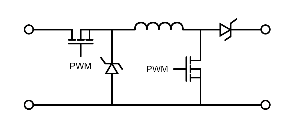
See how the buck boost circuit is really just a combination of buck and boost mode circuits. C1 to c3 are ceramic capacitors. Connect one terminal of inductor to source of mosfet and another to led in series with 1k resistor.
There are two types of converters in the buck boost converter that are buck converter and the other. Input voltage can be between 27 to 42v. Thus the input to the mosfet can be made through an optimized pwm circuit for getting the required transitions across the same circuit.
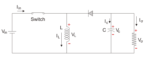
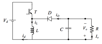
Load is connected in parallel to this arrangement. Assemble the circuit on a good quality pcb. The buckboost converter is a type of dc to dc converter that has an output voltage magnitude that is either greater than or less than the input voltage magnitude.
Assemble the circuit on a good quality pcb. Circuit diagram and connections. Following circuits may be also useful to you.
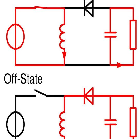
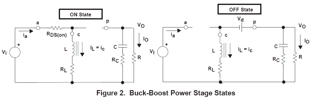
See the current paths during the on and off periods of the switching transistor in either mode. Connect 10k resistor between gate and source. It may be more or less than equal to the input voltage magnitude.
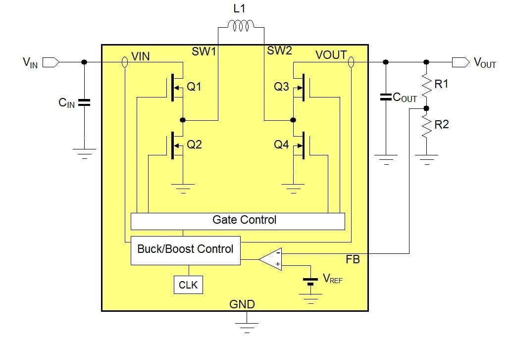
See how the operation of the circuit in both buck and boost modes can be controlled by a simple control unit. Make connections as shown in circuit diagram above for dc dc buck converter. L1 can be a toroid potcore or shielded bobbin inductor.
Buck boost converter circuit diagram. If d 05 the output voltage is larger than the input. Two different topologies are called buckboost converterboth of them can produce a range of output voltages ranging from much larger.
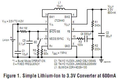
We know that d varies between 0 and 1. This is where the new ltc 3440 buckboost voltage converter from linear technology wwwlinear. It is a type of dc to dc converter and it has a magnitude of output voltage.
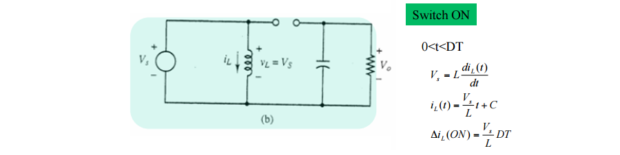
The inductance l is 50mh and the c is 100uf and the resistive load is 50w. The buck boost converter is equal to the fly back circuit and single inductor is used in the place of the transformer. Buckboost converter using ltc3440.
The switching regulator in figure 1 converts an input voltage in the range 27 v to 45 v into an output voltage in the range 25 v to 55 v using one tiny coil.
 An Ordinary Buck Boost Converter Circuit Using Matlab Simulink
 Analysis Of Four Dc Dc Converters In Equilibrium Technical Articles
 Dc To Dc Boost Converter Circuit Homemade
 Buck Boost Circuit Using Ic 555 Homemade Circuit Projects
 Advantages Of Buck Boost Converters
 Wide Vin And High Power Challenges With Buck Boost Converters
 Regulated Buck Boost Dc Dc Converter Circuit Electronics
 Buck Boost Converter Circuit Theory Working And Applications
 The Bidirectional Buck Boost Converter Circuit Diagram The Buck
 Buck Boost Converter Using Ltc3440 For An Output Voltage Of 3 3 Volts
 Buck Boost Converter Electrical4u
 Dc To Dc Buck Boost Converter Circuit Homemade การสอน
 Buck Boost Converter Circuit Theory Working And Applications
 Ltc3442 Buck Boost Converter Circuit
 Buck Boost Converters
 Dc To Dc Buck Boost Converter Circuit Homemade
 Buck Boost Topology How Buck Boost Converter Works
 Switching Circuits Buck And Boost Converters Savini
 Buck Boost Converter Electrical4u
 Fe 9317 And Buck Boost Converter Circuit Png File Rectifier And
 Microcontroller Based Bidirectional Buck Boost Converter For Photo
 How Inverted Buck Boost Boosts Bucks Electrical Engineering
 Buck Boost Converter With Pic Microcontroller And Ir2110
 Https Encrypted Tbn0 Gstatic Com Images Q Tbn 3aand9gcrszochjeduu4scxm13mi8qlpc3hl Oltkivecfkebyqvhjayz2 Usqp Cau
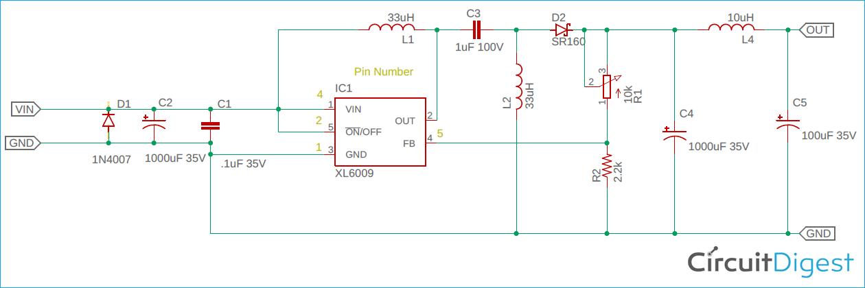 Buck Boost Regulator Circuit Design Using Xl6009 With Adjustable
 Buck Boost Converters
 General Buck Boost Converter Circuit Diagram Download
 What Is A Buck Boost Converter Quora
 Buck Boost Converter Buck Converter Dc To Dc Converter Voltage
 Buck Boost Converter Switching Dc Dc Regulator Electronics Notes
 File Basics Of The 4 Switch Buck Boost Converter Png Wikimedia
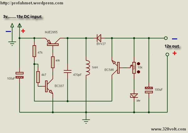
 5v To 12v Boost Converter Circuit Or Higher Eleccircuit Com
 Dc Dc Buck Boost Converter Youtube
 Buck Boost Regulator Average Output Voltage Expression Derivation
 Buck Boost Voltage Converter Schematic Circuit Diagram
 Dc To Dc Buck Boost Converter Circuit Homemade
 Buck Boost Converter Electrical Simple
 Advantages Of Buck Boost Converters
 Small Size Very High Efficiency Buck Boost Converter Youtube
 Buck Boost Converters
 Modeling And Controlling Strategy Of Four Switch Buck Boost
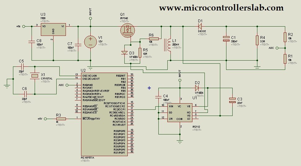 Buck Boost Converter With Pic Microcontroller And Ir2110
 How To Use Simple Converter Circuits Technical Articles
 An Ordinary Buck Boost Converter Circuit Using Matlab Simulink
 Buck Boost Voltage Converter Eeweb Community
 Buck Boost Converter File Exchange Matlab Central
 Buck Boost Converter Voltage Converter Buck Converter Electrical
 Boost Converter Circuit Using Mc34063 Ic
 Https Encrypted Tbn0 Gstatic Com Images Q Tbn 3aand9gcswztau8rdipb Zs7pzuxrblbdgi8uk1hy3qmdvhh10jzcep0xl Usqp Cau
 36v 2a Synchronous Buck Boost Converter And Led Driver
Buck Boost Voltage Converter Circuit Diagram
 Microcontroller Based Bidirectional Buck Boost Converter For Photo
 What Every Engineer Should Know About Buck Boost Converters
 Mc34063 Buck Converter Circuit Diagram Circuit Diagram Power
 4 Switch Buck Boost Converter Power Supply Circuit Circuit
 Variable Output Voltage Dc To Dc Boost Converter Circuit Diagram
 How To Make Buck Boost Converter In Simulink Matlab Technifi
 Charging Of Battery From Solar Supply Using Buck Boost Converter
 2 7v 4 2v Input To 3 3v Output Buck Boost Converter Electronics Lab
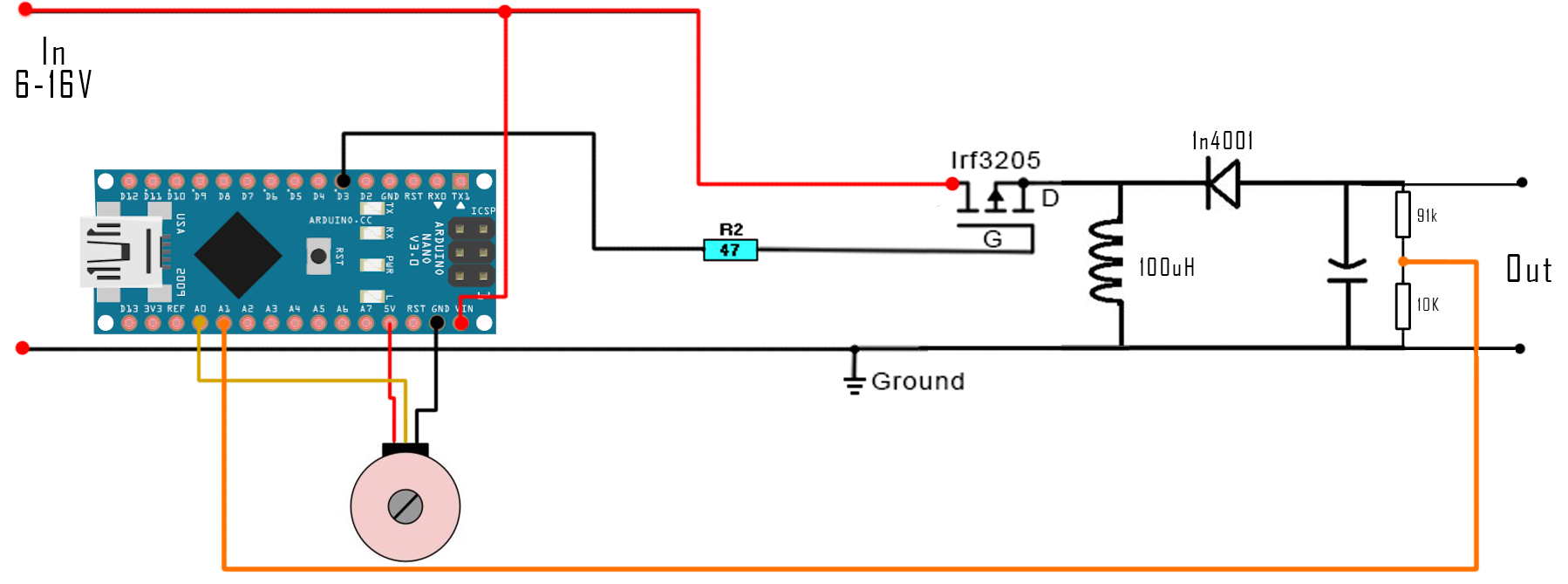
 Designing An Arduino Based Buck Boost Converter With Feedback
 Cs 1849 Buck Boost Converter File Exchange Matlab Central
 A Positive Buck Boost Dc Dc Converter With Mode Select Circuit
.png) How To Use Simple Converter Circuits Technical Articles
How To Use Simple Converter Circuits Technical Articles
 Analysis Converter Buck Boost Electrical Equipment Computer
 2 8vin To 22vin 2a Lout 4 Switch Integrated Buck Boost Converter
 4 Circuit Diagram Of Bidirectional Buck Boost Converter
 How To Control A Buck Boost Converter Circuit From A
 Buck Boost Buck Converters Stmicroelectronics
Buck Boost Converter Cosemitech Shanghai Co Ltd
 Buck Boost Converter Sandi Elektronik
 Figure 6 From Performance Analysis Of Unidirectional And
 Switch Mode Power Supply And Switching Regulators
 Designing Open Loop Non Isolated Inverting Buck Boost Converter
 Https Encrypted Tbn0 Gstatic Com Images Q Tbn 3aand9gcrszochjeduu4scxm13mi8qlpc3hl Oltkivecfkebyqvhjayz2 Usqp Cau
 How Buck Boost Circuits Work Homemade Circuit Projects
 Selecting A Step Up Down Buck Boost Converter Richtek Technology
 Diy Buck Boost Converter Flyback 5 Steps With Pictures
 Wiring Pre Circuit Diagram Buck Boost Voltage Converter
 How To Build An Arduino Based Buck Boost Converter Arduino
 Dc To Dc Buck Boost Converter Circuit Homemade
 Asian Economic And Social Society
 Designing Open Loop Non Isolated Inverting Buck Boost Converter
Dc Dc Converter Working Principle Ecri Microelectronics
 Buck Boost Voltage Converter Schematic Circuit Diagram
 Buck Boost Circuit Avr Freaks
 Mf 3565 Positive Buckboost Converter Circuit Diagram Tradeoficcom
 Buck Boost Converters Elsoc Wiki Fandom
 Breakthrough Buck Boost Controller Provides Up To 10a From A Wide
 Inverting Topology Buck Boost Converter Control Matlab Simulink
 Http Www Ijeei Org Docs 7734922695a72d68e0eec6 Pdf
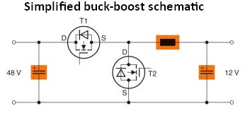 Vehicle Electrical Systems Zero To Sixty In 48 Volts
 Single Inductor Tiny Buck Boost Converter Power Supply Circuit
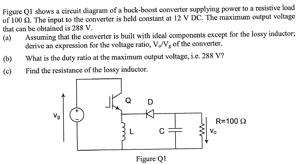 Solved Shows A Circuit Diagram Of A Buck Boost Converter
 Mp28164 Buck Boost High Efficiency Single Inductor Buck Boost
 Regulated Buck Boost Dc Dc Converter Circuit Electronics
 It Is Possible To Make A Non Inverting Buck Boost Converter With A
Boost Converter Wikipedia
 Chapter 8 Mplab Mindi Analog Simulator Peak Current Mode
 1
1
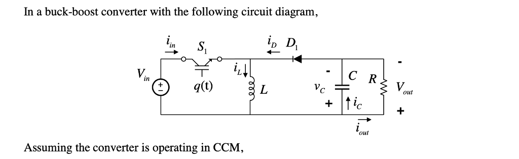 In A Buck Boost Converter With The Following Circu Chegg Com
 Mc34063 Boost Converter Circuit Converter Electronics Circuit
 Fundamental Circuit Diagrams Of Dc Dc Converters Types A Buck
 Lt3942 Synchronous Buck Boost Converter Linear Technology
Circuit Diagram Of Buck Boost Converter Download Scientific Diagram It is equivalent to a flyback converter using a single inductor instead of a transformer.
Circuit diagram buck boost converter. A circuit of a buck boost converter and its waveforms is shown below. Input voltage can be between 27 to 42v. Buck boost converter circuit diagram.
Buckboost converter using ltc3440. C1 to c3 are ceramic capacitors. With an increase in the mosfets on time the circuit starts getting transformed into a boost converter while with the mosfets off time exceeding its on time results in the circuit behaving like a buck converter.
It is a class of switched mode power supply smps typically containing at least two semiconductors a diode and a transistor although modern buck converters frequently replace the diode with a second transistor used for. And if d 05 the output is smaller than the inputbut if d 05 the output voltage is equal to the input voltage. L1 can be a toroid potcore or shielded bobbin inductor.
What is a buck boost converter. A buck converter step down converter is a dc to dc power converter which steps down voltage while stepping up current from its input supply to its output load. 5v buck regulator using lm2678.
See how the buck boost circuit is really just a combination of buck and boost mode circuits. C1 to c3 are ceramic capacitors. Connect one terminal of inductor to source of mosfet and another to led in series with 1k resistor.
There are two types of converters in the buck boost converter that are buck converter and the other. Input voltage can be between 27 to 42v. Thus the input to the mosfet can be made through an optimized pwm circuit for getting the required transitions across the same circuit.
Load is connected in parallel to this arrangement. Assemble the circuit on a good quality pcb. The buckboost converter is a type of dc to dc converter that has an output voltage magnitude that is either greater than or less than the input voltage magnitude.
Assemble the circuit on a good quality pcb. Circuit diagram and connections. Following circuits may be also useful to you.
See the current paths during the on and off periods of the switching transistor in either mode. Connect 10k resistor between gate and source. It may be more or less than equal to the input voltage magnitude.
See how the operation of the circuit in both buck and boost modes can be controlled by a simple control unit. Make connections as shown in circuit diagram above for dc dc buck converter. L1 can be a toroid potcore or shielded bobbin inductor.
Buck boost converter circuit diagram. If d 05 the output voltage is larger than the input. Two different topologies are called buckboost converterboth of them can produce a range of output voltages ranging from much larger.
We know that d varies between 0 and 1. This is where the new ltc 3440 buckboost voltage converter from linear technology wwwlinear. It is a type of dc to dc converter and it has a magnitude of output voltage.
The inductance l is 50mh and the c is 100uf and the resistive load is 50w. The buck boost converter is equal to the fly back circuit and single inductor is used in the place of the transformer. Buckboost converter using ltc3440.
The switching regulator in figure 1 converts an input voltage in the range 27 v to 45 v into an output voltage in the range 25 v to 55 v using one tiny coil.
An Ordinary Buck Boost Converter Circuit Using Matlab Simulink Analysis Of Four Dc Dc Converters In Equilibrium Technical Articles  Dc To Dc Boost Converter Circuit Homemade Buck Boost Circuit Using Ic 555 Homemade Circuit Projects Advantages Of Buck Boost Converters Wide Vin And High Power Challenges With Buck Boost Converters Regulated Buck Boost Dc Dc Converter Circuit Electronics Buck Boost Converter Circuit Theory Working And Applications The Bidirectional Buck Boost Converter Circuit Diagram The Buck Buck Boost Converter Using Ltc3440 For An Output Voltage Of 3 3 Volts Buck Boost Converter Electrical4u Dc To Dc Buck Boost Converter Circuit Homemade การสอน Buck Boost Converter Circuit Theory Working And Applications
  Ltc3442 Buck Boost Converter Circuit Buck Boost Converters
  Dc To Dc Buck Boost Converter Circuit Homemade Buck Boost Topology How Buck Boost Converter Works Switching Circuits Buck And Boost Converters Savini Buck Boost Converter Electrical4u Fe 9317 And Buck Boost Converter Circuit Png File Rectifier And Microcontroller Based Bidirectional Buck Boost Converter For Photo How Inverted Buck Boost Boosts Bucks Electrical Engineering Buck Boost Converter With Pic Microcontroller And Ir2110 Buck Boost Regulator Circuit Design Using Xl6009 With Adjustable Buck Boost Converters General Buck Boost Converter Circuit Diagram Download Buck Boost Converter Buck Converter Dc To Dc Converter Voltage Buck Boost Converter Switching Dc Dc Regulator Electronics Notes File Basics Of The 4 Switch Buck Boost Converter Png Wikimedia 5v To 12v Boost Converter Circuit Or Higher Eleccircuit Com Dc Dc Buck Boost Converter Youtube Buck Boost Regulator Average Output Voltage Expression Derivation Buck Boost Voltage Converter Schematic Circuit Diagram
  Dc To Dc Buck Boost Converter Circuit Homemade
  Buck Boost Converter Electrical Simple Advantages Of Buck Boost Converters Small Size Very High Efficiency Buck Boost Converter Youtube Buck Boost Converters Modeling And Controlling Strategy Of Four Switch Buck Boost Buck Boost Converter With Pic Microcontroller And Ir2110 How To Use Simple Converter Circuits Technical Articles An Ordinary Buck Boost Converter Circuit Using Matlab Simulink Buck Boost Voltage Converter Eeweb Community Buck Boost Converter File Exchange Matlab Central Buck Boost Converter Voltage Converter Buck Converter Electrical
  Boost Converter Circuit Using Mc34063 Ic 36v 2a Synchronous Buck Boost Converter And Led Driver
 Buck Boost Voltage Converter Circuit Diagram
Microcontroller Based Bidirectional Buck Boost Converter For Photo What Every Engineer Should Know About Buck Boost Converters Mc34063 Buck Converter Circuit Diagram Circuit Diagram Power  4 Switch Buck Boost Converter Power Supply Circuit Circuit Variable Output Voltage Dc To Dc Boost Converter Circuit Diagram How To Make Buck Boost Converter In Simulink Matlab Technifi Charging Of Battery From Solar Supply Using Buck Boost Converter 2 7v 4 2v Input To 3 3v Output Buck Boost Converter Electronics Lab Designing An Arduino Based Buck Boost Converter With Feedback Cs 1849 Buck Boost Converter File Exchange Matlab Central A Positive Buck Boost Dc Dc Converter With Mode Select Circuit How To Use Simple Converter Circuits Technical Articles Analysis Converter Buck Boost Electrical Equipment Computer
  2 8vin To 22vin 2a Lout 4 Switch Integrated Buck Boost Converter 4 Circuit Diagram Of Bidirectional Buck Boost Converter How To Control A Buck Boost Converter Circuit From A Buck Boost Buck Converters Stmicroelectronics
 Buck Boost Converter Cosemitech Shanghai Co Ltd
 Buck Boost Converter Sandi Elektronik Figure 6 From Performance Analysis Of Unidirectional And Switch Mode Power Supply And Switching Regulators Designing Open Loop Non Isolated Inverting Buck Boost Converter How Buck Boost Circuits Work Homemade Circuit Projects Selecting A Step Up Down Buck Boost Converter Richtek Technology Diy Buck Boost Converter Flyback 5 Steps With Pictures
  Wiring Pre Circuit Diagram Buck Boost Voltage Converter How To Build An Arduino Based Buck Boost Converter Arduino
  Dc To Dc Buck Boost Converter Circuit Homemade
  Asian Economic And Social Society Designing Open Loop Non Isolated Inverting Buck Boost Converter
 Dc Dc Converter Working Principle Ecri Microelectronics
Buck Boost Voltage Converter Schematic Circuit Diagram Buck Boost Circuit Avr Freaks Mf 3565 Positive Buckboost Converter Circuit Diagram Tradeoficcom Buck Boost Converters Elsoc Wiki Fandom Breakthrough Buck Boost Controller Provides Up To 10a From A Wide Inverting Topology Buck Boost Converter Control Matlab Simulink Vehicle Electrical Systems Zero To Sixty In 48 Volts  Single Inductor Tiny Buck Boost Converter Power Supply Circuit Solved Shows A Circuit Diagram Of A Buck Boost Converter Mp28164 Buck Boost High Efficiency Single Inductor Buck Boost Regulated Buck Boost Dc Dc Converter Circuit Electronics Boost Converter Wikipedia Chapter 8 Mplab Mindi Analog Simulator Peak Current Mode In A Buck Boost Converter With The Following Circu Chegg Com Mc34063 Boost Converter Circuit Converter Electronics Circuit Fundamental Circuit Diagrams Of Dc Dc Converters Types A Buck Lt3942 Synchronous Buck Boost Converter Linear Technology


