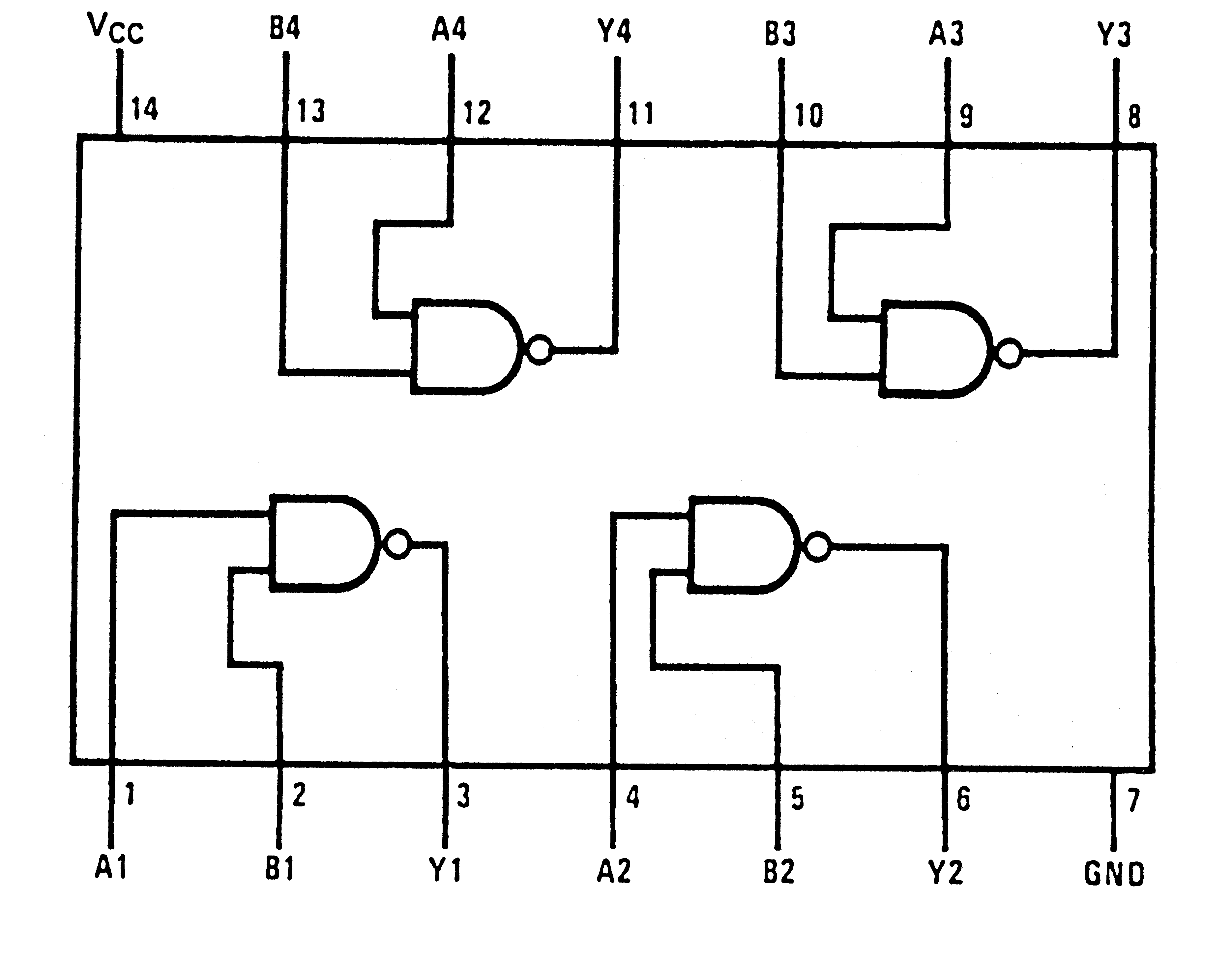
Circuit Diagram And Gate
So in calculators computers and manly digital applications use this gate. See below for more detailed instructions.
And Gate Circuit Diagram Working Explanation
The following is a list of 7400 series digital logic integrated circuitsthe original 7400 series integrated circuits were made by texas instruments with the prefix sn to create the name sn74xx.
Circuit diagram and gate. Combinational circuit is a circuit in which we combine the different gates in the circuit for example encoder decoder multiplexer and demultiplexer. On a circuit diagram it must be accompanied by a statement asserting that the positive logic convention or negative logic convention is being. A free simple online logic gate simulator.
The circle on the symbol is called a bubble and is used in logic diagrams to indicate a logic negation between the external logic state and the internal logic state 1 to 0 or vice versa. Build and simulate circuits right in your browser. Professional schematic pdfs wiring diagrams and plots.
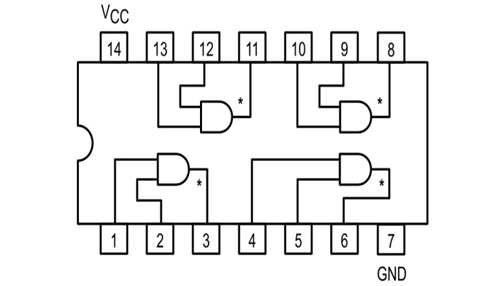
Lets look at the or gates truth diagram. Here we are going to use ic 74ls09 for demonstration this chip has 4 and gates in it. In electronics a not gate is more commonly called an inverter.
Launch simulator learn logic design. Right click connections to delete them. The logic gates can be build up in a wide variety forms such as large scale integrated circuits lsi very large scale integrated circuits vlsi and also in small scale integrated circuits ssi.
Drag from the hollow circles to the solid circles to make connections. For teachers for contributors. Due to the popularity of these parts other manufacturers released pin to pin compatible logic devices which kept the 7400 sequence number as an aid to identification of compatible parts.
The circuit symbol is that arrowhead kind of shape and inputs and outputs are marked the same way as the and gate. Design circuits online in your browser or using the desktop application. Here the inputs and output of all the gates of integrated devices can be accessible and also the external connections are made available to them.
This gate is mainly used in applications where there is a need for mathematical calculations. Design with our easy to use schematic editor. From simple gates to complex sequential circuits plot timing diagrams automatic circuit generation explore standard ics and much more.
16 bit ripple carry adder. Select gates from the dropdown list and click add node to add more gates. Symbols for most commonly used components are included from resistors and capacitors to logic gates and transistors.
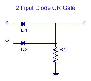
Some of the characteristics of combinational circuits are following the output of combinational circuit at any instant of time depends only on the levels present at input terminals. Analog digital circuit simulations in seconds. Another type of logic gate is the or gate.
As you can see as long as any one of the inputs is 1 the output will be 1 and only if all inputs are 0 will the result be 0. Launch circuitlab or watch a quick demo video. Launch it instantly with one click.
Investigate the behaviour of and or not nand nor and xor gates. Circuit diagram is a free application for making electronic circuit diagrams and exporting them as images. These four gate are connected internally as shown in below pin diagram.
 Logic And Gate Tutorial With Logic And Gate Truth Table
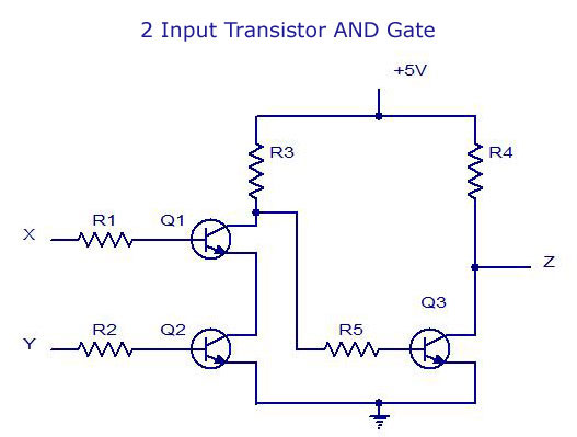 Digital Electronics Logic Gates Basics Tutorial Circuit Symbols
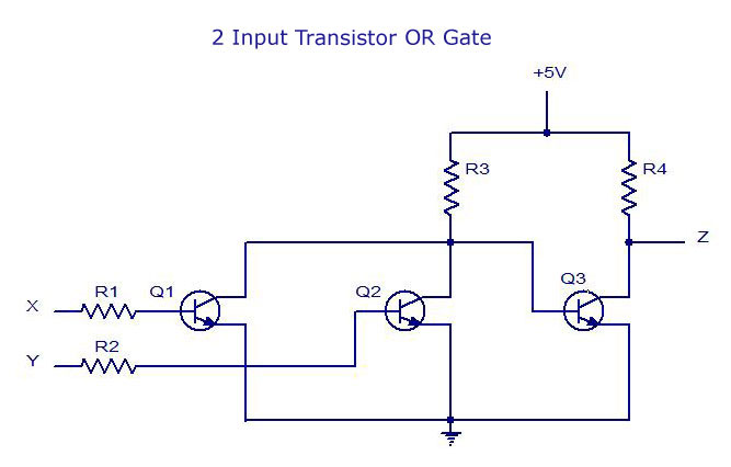 Digital Electronics Logic Gates Basics Tutorial Circuit Symbols
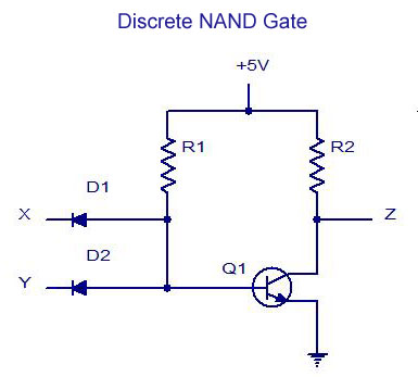 Digital Electronics Logic Gates Basics Tutorial Circuit Symbols
 Digital Electronics Logic Gates Basics Tutorial Circuit Symbols
Https Encrypted Tbn0 Gstatic Com Images Q Tbn 3aand9gctpfxfmpe3l 97h8g2egyg Rxntgzfi1gjgtw Usqp Cau
 Logic Or Function Digital Logic Gates
 Multiple Input Gates Logic Gates Electronics Textbook
 Https Encrypted Tbn0 Gstatic Com Images Q Tbn 3aand9gcrarpardclop4g03eqctjof8sftnh8aof6 Ba Usqp Cau
 Lessons In Electric Circuits Volume Iv Digital Chapter 3
 Mux Logic Gate Circuit Diagram Template Logic Templates
 And Gate Circuit Diagram Working Explanation
 Not Gate Circuit Diagram Circuit Diagram Electronics Circuit
 Logic Gate Circuit Diagram Xor Gate And Gate Electronic Symbol
Kelen Tengok Aja Dulu Logical And Gate
 Logic Gate Types Including Circuit Diagram Symbols And Uses
Combinational Circuit Logic Gate Diagram
Electronics Tutorial Sections 6 12
 What Is The Difference Between Logic Gates And Integrated Circuits
 Basic Logic Gates Using Nand Gate Eeweb Community
 Circuit Diagram To Design And Gate Using Npn Transistor
 Ng 4984 Digital Logic Simple Nor Gate Transistorlevel Diagram
 Combinational Logic Circuits Using Logic Gates
 Cmos Xor Gate Circuit Diagram Download Scientific Diagram
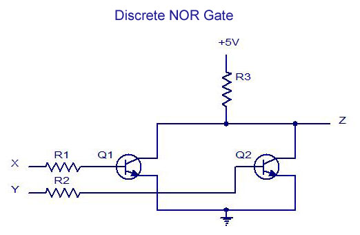 Digital Electronics Logic Gates Basics Tutorial Circuit Symbols
 Logic Gates And Its Types Pgclasses With Ravishankar Thakur
 Lessons In Electric Circuits Volume Iv Digital Chapter 3
Electronics Tutorial Sections 6 12
 Full Adder Logic Gate Circuit Diagram Template Logic Circuit
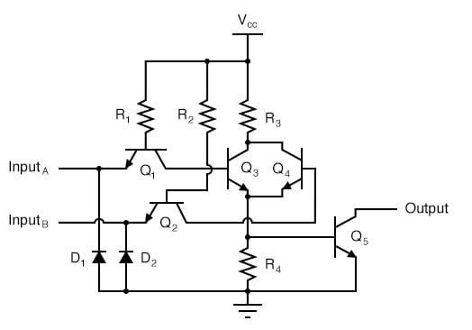 Ttl Nor And Or Gates Logic Gates Electronics Textbook
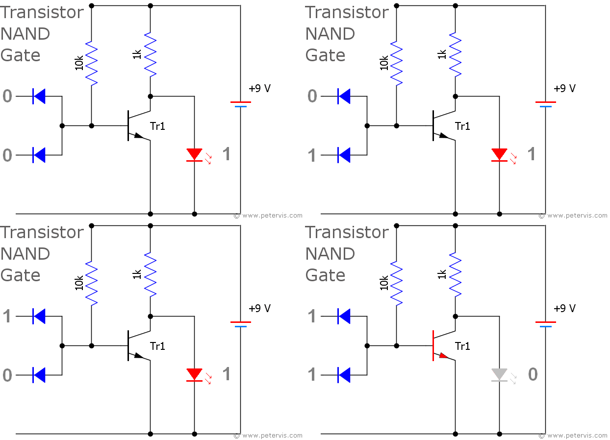 Https Encrypted Tbn0 Gstatic Com Images Q Tbn 3aand9gcsph Wiuqerqzlz7e Vkrvyiv Fobyzmoya Usqp Cau
How Are Nand Gate And Nor Gate Represented With Switches And Lamps
 Schematic Diagram And Layout Of Two Input Nand Gate Youtube
 Flip Flop Nand Gate Logic Gate Truth Table Nor Gate Circuit
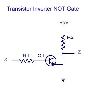 Digital Electronics Logic Gates Basics Tutorial Circuit Symbols
 Download Free Png Logic Gate Circuit Diagram Xor Gate And Gate
Circuit Diagram Of Inverter And Nand Gate Download Scientific
 Logic Gate Circuit Diagram Wiring Diagram Decircuit Gates
 Introduction To Nor Gate Projectiot123 Technology Information
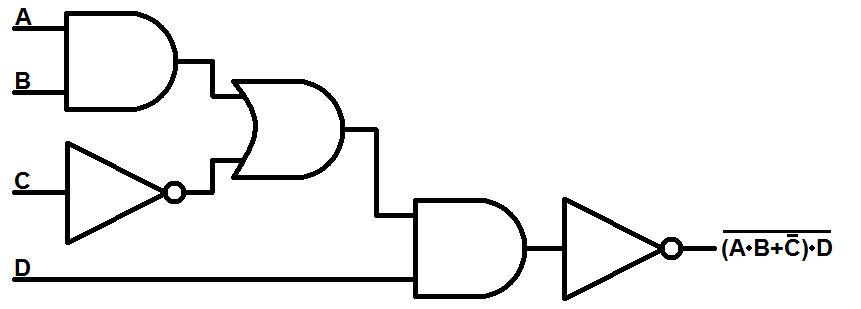 Logicblocks Digital Logic Introduction Learn Sparkfun Com
 Schematic Diagram Of Gate Control Theory Of Pain Mechanisms 10
7402 Pinout And Circuit Diagram Logic Gate Ics Hqew Net
 Wiring Diagram For Gate Automation Gate Operator With Entrance
 Flip Flop Nand Gate Logic Gate Truth Table Nor Gate Circuit
 Wiring Diagram For Gate Automation Gate Operator With Telephone
 13 Small Digital Circuit Ideas For Beginner Digital Circuit
 Schematic Diagram And Layout Of And Or Invert Aoi Gate Youtube
 Lessons In Electric Circuits Volume Iv Digital Chapter 3
 Control 7404 Not Gate Ic Using Arduino Mega Funny Electronics
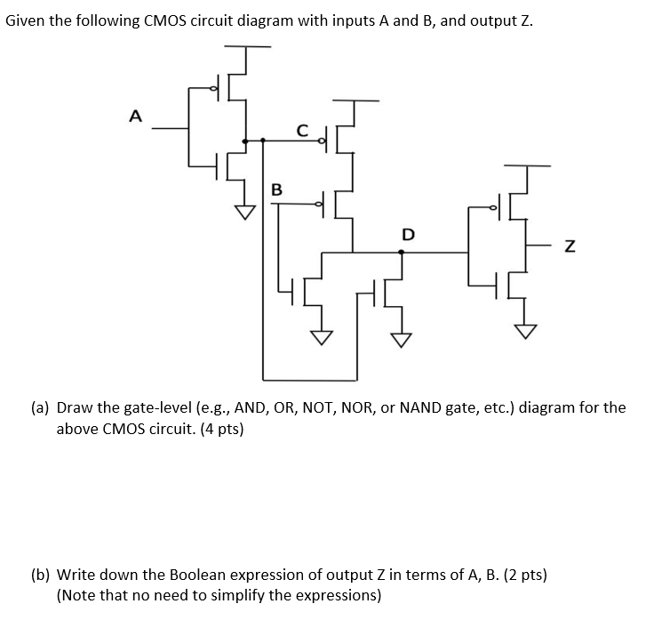 Solved Given The Following Cmos Circuit Diagram With Inpu
 Sequential Logic Circuit Diagram Diagram Base Website Circuit
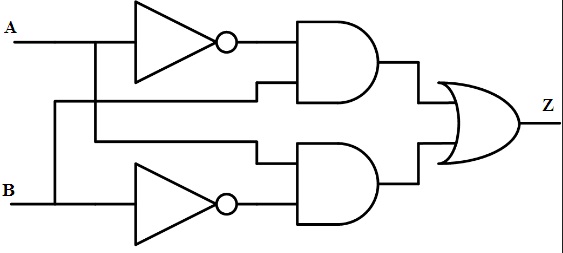 Logic Gate Types Including Circuit Diagram Symbols And Uses
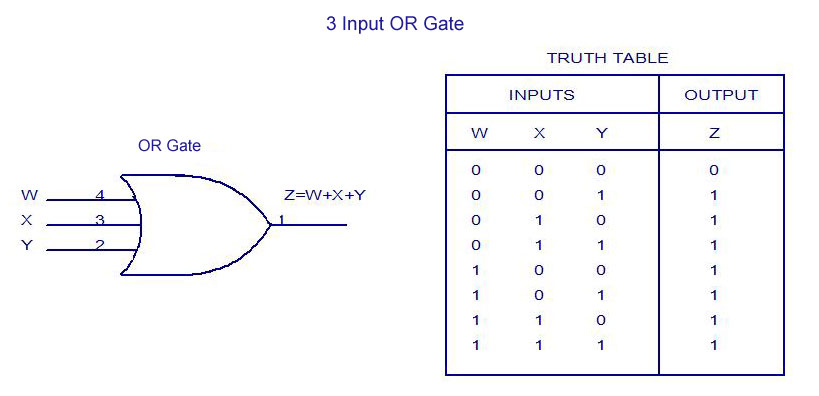 Digital Electronics Logic Gates Basics Tutorial Circuit Symbols
 Circuit Diagram For Majority Gate Where X0 X1 X2 Are A B C
What Is The Logic Switching Circuit Of Xor And Xnor Gates Quora
 Gates Cirq 0 8 0 Documentation
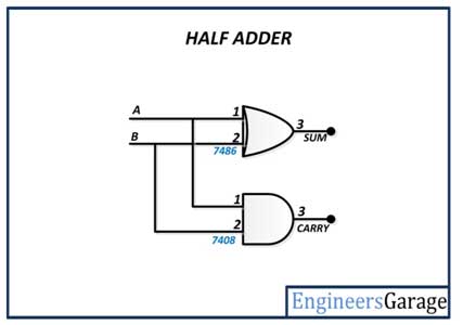 Logic Gate Implementation Of Arithmetic Circuits De Part 11
How To Build A Diode And Gate Circuit
 Basic Logic Gates Using Nand Gate Nand Gate Logic Basic
Quantum Circuit Diagram Of Step 1 A Denotes The 2sin 2 P
 Gsm Remote Control Gate Control Part 2 Schematic Open
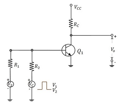 Bidirectional Sampling Gates Tutorialspoint
 Https Encrypted Tbn0 Gstatic Com Images Q Tbn 3aand9gcsrgnuwsfndq7quc7yxjmhwwat6xpsrs4riow Usqp Cau

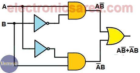 Xor Gate Tutorial Boolean Function And Truth Table Electronics Area
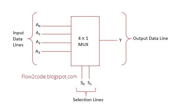 Circuit Diagram Logic Gates F7 Wiring Diagram
 Ic 7400 Pin Configuration Circuit Specifications And Its
Https Encrypted Tbn0 Gstatic Com Images Q Tbn 3aand9gct3hs Bgs1fc0mgy4d6n1qzbz M28abavynbn8ghzm3bmkydeuy Usqp Cau
 Circuit Diagram Of Xor Gate Easyeda
 Circuit Diagram De Morgan S Laws Logic Gate Schematic Scientific
 Lessons In Electric Circuits Volume Iv Digital Chapter 3
 File Simplified Nand Gate Circuit Using 2 Transistors Svg
 Circuit Diagram And Output Waveform Of 3t And Gate Download
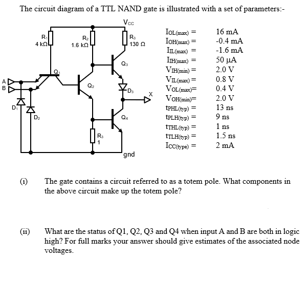 Solved The Circuit Diagram Of A Ttl Nand Gate Is Illustra
 Basic Gate Function Digital Integrated Circuits Electronics
How Does A Not Gate Work At The Circuit Level Quora
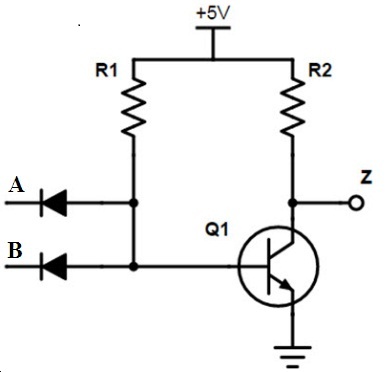 Logic Gate Types Including Circuit Diagram Symbols And Uses
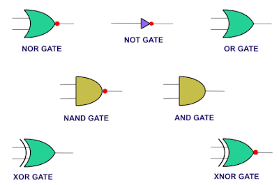 What Is Logic Gate Or Digital Circuit With Truth Table And
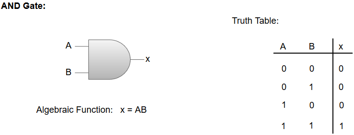 Logic Gates Computer Organization And Architecture Tutorial
 Rn 1094 And Gate Circuit Diagram
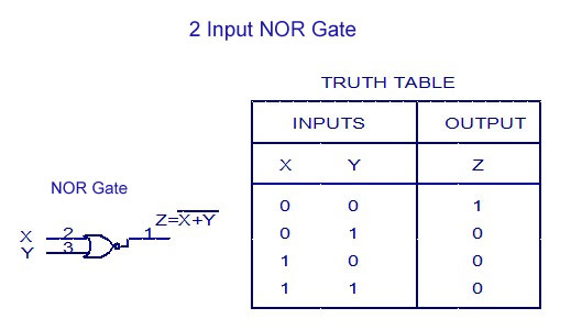 Digital Electronics Logic Gates Basics Tutorial Circuit Symbols
 Discrete Ttl Nand Gate Bigcode

 Circuit Diagram Logic Gates F7 Wiring Diagram
 Emitter Coupled Logic Logic Gate Electronic Circuit Circuit
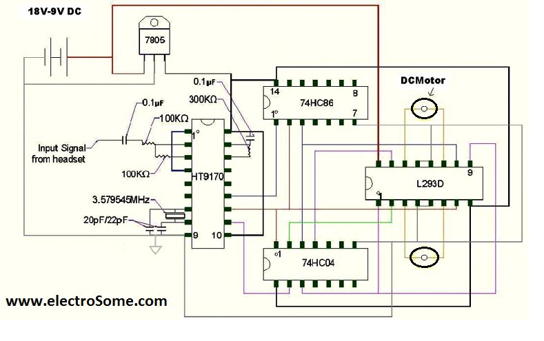 Cell Phone Controlled Land Rover Using Logic Gates
 Implementing Logic Functions Using Only Nand Or Nor Gates Eeweb
 Automatic Railway Gate Control System With High Speed Alerting
Smartecremote Gate Door Opener Schematics Circuit Diagram Smart
Day 27 Gate Logic Practice Write The Truth Table And Circuit
Transmission Gate With Body Effect Compensation Circuit Diagram
![]() Circuit Diagram Electric Electronic Logic Gate Nor Nor Gate Icon
Circuit Diagram Electric Electronic Logic Gate Nor Nor Gate Icon
Https Encrypted Tbn0 Gstatic Com Images Q Tbn 3aand9gcressnjjgcrfjj Lpyhp5ei66pcbjrkus1gx Qshkl9ywoh598n Usqp Cau
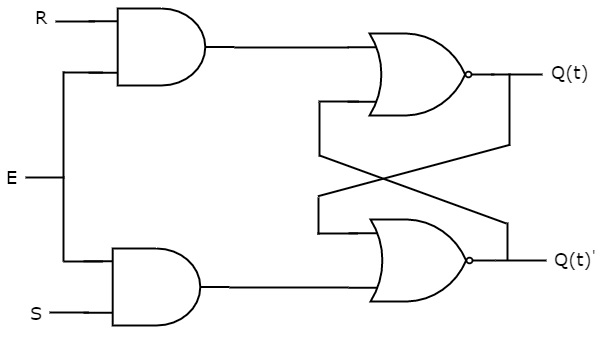 Digital Circuits Latches Tutorialspoint
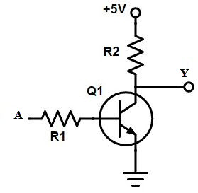 Not Gate Symbol Truth Table Realization Electricalvoice
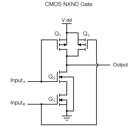 Cmos Gate Circuitry Logic Gates Electronics Textbook

